Chủ Nhật, 16 tháng 1, 2011

Để làm âm thanh cho một Big show, sound man cần gì!

Để có một show hoành tráng chất lượng ngoài những thiết bị PA chuyên nghiệp thì Amply xịn cho guitar và Bass là ko thể thiếu.
Trống, Bass và Guitar là những nhạc cụ linh hồn của dàn nhạc, khi cái gốc không ngon thì tổng thể có đạt được?
Trước đây tất cả amp cho guitar và bass đều do nhạc công tự trang bị nên rất hạn chế về tài chính ko thể có những amp pro, và hơn nữa những sound man ko hiểu rõ về amp và cách xử lý nên chất lượng của dàn nhạc rất thấp.
Hiện nay đã có một số cty đâu tư guitar amp và bass amp tốt như Fantasy có 2 amp guitar marshall JCM2000 và Marshall JCM800, 01 bass amp Ampeg, do đó những big show hiện nay fantasy làm khá hay.

Trong show ROckStorm cuối năm 2007 do fantasy làm âm thanh có thuê một sound man người Japan kết quả là âm thanh của show rất tốt, các band nhạc rất hài lòng. Qua tiết xúc với anh tôi nhận thấy rằng một sound man ko chỉ hiểu biết nắm rõ về các thiết bị PA mà còn phải thực sự hiểu biết về từng nhạc cụ như trống, bass, guitar. Có thẩm mỹ cao về âm thanh của các nhạc cụ, nắm rõ cơ chế hoạt động của từng nhạc cụ hiểu rõ tâm lý biểu diễn của các nghệ sỹ trên sân khấu, cao hơn nữa là hiểu biết về sound của các dòng nhạc khi có nhiều band nhạc khác nhau cùng chơi những dòng nhạc khác nhau.


Các ban nhạc nổi tiếng nước ngoài đều có sound man riêng ( 2 người, 1 làm FOH, 1 làm Monitor) nên ngoài việc kỹ thuật cao họ còn rất hiểu nhau và hiểu các thành viên của band.
Họ hiểu từng bài, từng cách chơi của các thành viên và đặc biệt là âm thanh mong muốn của từng người chơi.Tốt nhất là âm thanh người nghệ sỹ muốn tạo ra thế nào, khi hòa âm trong cả band sẽ thế nào người làm âm thanh phải mang tới người nghe như thế. Tất nhiên người nghệ sỹ và sound man cũng phải trao đổi góp ý với nhau thường xuyên. 


Ở VN thì sự phối hợp và hợp tác ko tốt, sound man thì ngại trao đổi hỏi ý kiến nhạc công, ca sỹ, nhạc công và ca sỹ thì...

Sound man còn phải phối hợp với người tổ chức, người thiết kế sân khấu, band... để bố trí vị trí của band, trống, loa monitor...

Ở VN...


Ở VN thì nhiều khi Ông thiết kế không có kinh nghiệm về biểu diễn live show, vể âm nhạc... bố trí, thiết kế lung tung, theo sở thich cá nhân hoặc ...chiều theo nhà tài trợ.
Có khi bố trí bục trống để quá xa guitar, keyboad...( quốc tế họ có tiêu chuẩn xa tối đa theo chiều ngang và dọc là bao nhiêu...bác nào cần email cho e).
Có khi lại bắt đặt bàn mixer FOH ngang sân khấu hoặc đôi khi sau sân khấu...thật ngu ngốc khi họ lý luận là khách hàng yêu cầu hoặc là công ty âm thanh này kia có sound man có thể làm được...tất nhiên là có thể làm được nhưng chất lượng thì ko thể hay được mà người làm rất khó chịu ( như la điếc hoặc bịt tai ma làm âm thanh vậy).
Người sound man nghe được âm thanh đầy đủ và hay thì mới sảng khoái và hứng thú để làm tôt ( vì vậy chỗ đặt bàn Mixer âm thanh phải là chỗ tốt nhất để nghe ( giữa không gian phia trước và cách sân khấu từ 30-60m tùy địa điểm tổ chức.


Có nhiều chương trình loa còn phải đặt sau màn hình Projector nưa kia. Các bác tưởng tượng loa ma lấy tấm vải bạt trùm kín phía trước thì nghe no thế nào??? bọn e cũng vì tiền mà làm thôi chứ nếu ko thì chẳng thèm làm, làm mà bản thân mình thấy tệ cũng chán lắm chứ...

Còn sound man cho monitor phải làm tiêu chuẩn và kỹ thuật chung nhưng cũng phải chiều theo sở thích riêng của từng cá nhân trong band và cả band để làm sao band nghe tốtm hay, có thế họ mới chơi hay và thỏa mãn khán giả.

Tóm lại là cả sound man và band đều phải hiểu yêu cầu cơ bản để set up một live show và phải tôn trong phối hợp với nhau.

Ở VN nhiều band rất "cá tính", guitar cứ chạy lung tung để thể hiện.
Anh có thể chạy nhảy, thay đổi vị trí nhưng với 2 điều kiện: một là anh phải bàn bạc với sound mand để họ bố trí loa monitor ở những vị trí mới của anh, hai là anh phải là người chơi rất điêu luyện và cả band của anh đã tập luyện trước những tình huống đó vì trên sân khấu trong lúc biểu diễn rất ồn, nếu ko có monitor a ko thể nghe rõ anh chơi như thế nào và đặc biệt ca sỹ và band a chơi ra sao, làm sao a có thể chơi đúng nhip? khi a sai nhip thì những người theo nhip của a cũng sai nốt, thế thì làm sao ma hay được??? bảo sao nhiều khán giả ko hiểu cứ nói là band này chơi hay lắm nhưng hôm nay ko hay là do âm thanh...

====
Có một tình huống nữa đáng lưu ý là monitor cho các thành viên ban nhạc và ca sỹ ( đặc biệt là rock show) phải có tín hiệu được mix riêng biệt sao cho khi cần có thể điều chỉnh thêm bớt âm lượng, effect, loại âm thanh nhạc cụ nào cần...mà ko hề ảnh hưởng tới các loa monitor khác. Ví dụ tôi chơi guitar bass, tôi chắc chắn là phải nghe rõ tiếng đàn của tôi trong loa monitor của tôi, tôi cũng cần phải nghe tiếng kick, snare để theo nhip, tiếng các nhạc cụ khác có thể bé hơn thậm chí ko cần vì tôi có thể nghe nho nho từ loa monitor của họ...
Các bác cứ tưởng tượng ông guitar bass lúc nào hứng chí chạy sang giao lưu với ông guitar lead ông ta sẽ ko nghe thấy tiếng của mình ( vì ông guitar lead ko cần nghe hoặc chỉ cần nghe nhỏ tiếng bass) thế là ông ấy đánh sai, đánh lung tung và...đổ thừa là âm thanh ko hay hoặc sound man kém. Thế giới người ta cũng chạy lung tung giao lưu nhưng người ta rất thành thạo, tập với nhau nhiều lần và trao đổi kỹ với sound man để khi đó tự động sound man tănng volume hoặc cho tiếng bass vào monitor của người mà anh sang giao lưu( đừng nghĩ là họ biểu diễn tự nhiên, càng chuyên nghiệp càng phải có kịch bản chi tiết và phải tuân thủ nghiêm túc). Tóm lại là mọi cái phải co kịch bản và chuẩn bị trước nếu ko những thành viên trong band sẽ khó chịu với anh, sau đó la khán giả sẽ phát hiện ra âm thanh lộn xộn, sound man sẽ tức tối với a...show diễn sẽ ko thành công vì anh...trừ khi anh là ngôi sao...

====
Hay ... nhà em chỉ tuyền bán đồ, cái môn đánh tươi tại trận (live show) ntn rất kém ...
Bác Hưng có cái gì hay hay thì mail cho em nhé phamchikien@nhanan.com.vn, phamchikien@fpt.vn .... thanks bác nhiều.
Lúc nào em bẩu mấy chú kỹ thuật dự án của em qua bác chỉ cho ít kinh nghiệm đánh sâu nhá ...

Mấy cái bác Hưng hỏi em thì lô hàng ấy lại là cho dự án nên cân giấy tờ NK >> thuế NK & VAT phải đóng đủ >>> về đến VN giá không hợp lý cho cá nhân nên em không ới bác . Lần dau có lô nào không cần chứng từ em sẽ ới bác há ...

====

Ở VN nhiều band rất "cá tính", guitar cứ chạy lung tung để thể hiện.
Anh có thể chạy nhảy, thay đổi vị trí nhưng với 2 điều kiện: một là anh phải bàn bạc với sound mand để họ bố trí loa monitor ở những vị trí mới của anh, hai là anh phải là người chơi rất điêu luyện và cả band của anh đã tập luyện trước những tình huống đó vì trên sân khấu trong lúc biểu diễn rất ồn, nếu ko có monitor a ko thể nghe rõ anh chơi như thế nào và đặc biệt ca sỹ và band a chơi ra sao, làm sao a có thể chơi đúng nhip? khi a sai nhip thì những người theo nhip của a cũng sai nốt, thế thì làm sao ma hay được??? bảo sao nhiều khán giả ko hiểu cứ nói là band này chơi hay lắm nhưng hôm nay ko hay là do âm thanh...


Loạt bài viết hay quá, xin cảm ơn bác Funktion one, nhân tiện bác cho em hỏi bởi em hơi thắc mắc là Guitarist cắm dây từ đàn vô bàn trộn, còn trên tai thường đeo Monitor/không dây, như vậy anh ta có di chuyển đi đâu trên sân khấu cũng vậy thôi, sao phải bố trí chuyển loa theo ạ ?


Thời gian qua nhanh quá, mới đó mà cái thời đàn ca sáo thổi đã ngót 20 năm rồi. Anh em VNAV homnafo tổ chức đại nhạc hội đi, mấy bác toàn đánh lẻ hát bàn tay vàng không hà, lụt nghề hết rồi nè.


Xin cảm ơn bác và mời tiếp tục ạ.


====
Việc sử dụng IEM gần đây mới trở nên phổ biến vì những lý do sau( đây là em trao đổi với các sound man quốc tế vì e chưa có hệ thống đó và cũng chưa có nhiều kinh nghiệm):
Ưu điểm:
- Sân khấu nhìn sạch sẽ hơn, nhất là những show truyền hình, show rock live rất it dùng.
- Người dùng có thể đi lại tự do hơn ( ca sỹ vẫn phải lưu ý vì vẫn có hiện tượng feedback).
- Chi phí rẻ hơn, 1 bộ của shure gồm cả tai nghe khoảng 2200usd, nếu dùng hệ thống của Fantasies hiện nay: loa NexoPS15 2200usd/1c processor Nexo 1000usd/c, 1 channel Amp ( nếu đánh full) 1800usd/2=900usd, dây jack linh tinh 200usd, tổng cộng khoảng 4300usd ( comp, gate, eq thì cả 2 loại đều cần dùng. Một band có bao nhiêu người sẽ phải dùng bấy nhiêu bộ.
- Ít bị feed back từ loa monitor hơn, đặc biệt hữu ích khi biểu diễn ở phòng kín nhiều feedback, tiếng um như nhà A3 Giảng võ Hà nội...


Nhược điểm:
- Âm thanh các nhạc cụ nghe ko hay bằng vì dùng IEM người nhạc công nghe âm thanh mình chơi ko thật nên rất khó cho ra được tiếng mình mong muốn. Một ví dụ rất điển hình là người chơi guitar lead chẳng hạn, bình thường anh ta có một loa chỉ cho ra tiếng của mình ( thường là loa Marhall) và một loa monitor để nghe tiếng các nhạc cụ khác( và có thể cả tiếng của mình), anh ta sẽ tự điều chỉnh đàn, effect, amply Marshall trong lúc biểu diễn để có được âm thanh mong muốn còn sound man chỉ việc lấy micro SM58 hoặc các loại đặc biệt khác để lấy âm thanh đó mix lại, nếu a ta dung IEM thì sẽ ko dung Marshall nữa và khi đó âm thanh phát ra anh ta ko tự điều chỉnh được nhiều nên kém hay đặc biệt la khi chơi rock.
- Âm thanh nhạc công nghe bằng IEM sẽ bị delay ít nhiều nên sự phối hợp cả band cũng ko tôt.
- Đặc biệt quan trọng là cảm giác người chơi như bị tách biệt với cả band, với khán giả nên giảm sự hưng phấn, thăng hoa nên...chơi kém hay.


Vậy khi đi nghe rock các bác cần nghe hay or nhìn đẹp???


====
Guitarist cắm dây từ đàn vô bàn trộn, còn trên tai thường đeo Monitor/không dây, như vậy anh ta có di chuyển đi đâu trên sân khấu cũng vậy thôi, sao phải bố trí chuyển loa theo ạ ?


E quên chư trả lời bác cụ thể.
Khi anh đã dùng IEM thì cần gì phải có loa monitor nữa vì a có nghe được đâu???
Khi ko dùng IEM và sân khấu thiết kế đặc biệt, anh muốn di chuyển tới chỗ nào đó để đảm bảo chất lượng trình diễn sound man sẽ phải bố trí loa monitor ở đó cho anh và tất nhiên khi nào anh đến đó thì sound mand mới đẩy fader mở to lên để anh nghe rõ còn bình thường có thể tắt để khỏi làm ồn sân khấu, gây thêm feedback, gây nhiễu tới các nhạc công khác( vì vị trí loa đặt cách xa nhau sẽ có hiện tượng delay gây khó khăn trong việc nghe để chơi nhạc.


E xin lấy một ví dụ ở mình ca sỹ rất hay chạy lung tung, thậm chí chạy xuống chỗ khán giả trong lúc đang hát. Lúc đó ai là người đi nghe nhạc ( không phải là đi xem) thì cực kỳ khó chịu vì âm thanh thì bị vọng( delay) ca sỹ thì hát sai nhip...thật ko tôn trọng khán giả đi nghe nhạc, chỉ thu hút những người đi xem thôi...


====
Hiện nay những chương trình nhỏ( ko phải rock show) và một số chương trình Rock do kinh phí ít hoặc vì ly do gì đó người ta vẫn sử dụng hệ thống monitor chung 1mix cho cả band (quốc tế gọi là mix, nếu 2 đường gọi là 2mix, 8 người nhạc công dùng 8 đường riêng biệt gọi là 8mix).
Nên khi nhạc công hoặc ca sỹ yêu cầu nhạc cụ nào đó to lên hoặc bé đi hoặc bỏ hẳn tiếng trong monitor của họ thì...chịu vì nếu bỏ đi thì tất cả các monitor đều bị ảnh hưởng nên band sẽ rất khó chiu( mỗi người một yêu cầu và sở thích khác nhau).
Hoặc tôi thích nghe to, anh thich nghe bé...người làm âm thanh sẽ bó tay...
Hơn nữa khi tất cả các loa có tiếng giống nhau lại mở to thì trên sân khấu âm thanh monitor se rất ồn, các nhạc công nghe ko được rõ, nhiều feedback...cuối cùng la ko hay và hay cãi lôn với nhau và với sound man...đặc biệt là với rock show.
Chính vì thế để một show diễn đảm bảo, chi phí cho phần monitor ko ít hơn phần FOH.


Ví dụ: show có 7 nhạc công và 1 ca sỹ
FOH: 1 mixer, 2 effect, 1 EQ, 1 processor, 10amp, 20 loa
Monitor: 8 người cần 8 mix, 1 mixer có ít nhất 8aux, 2-8 channel effect, 8channel EQ, 8 channel comp, 8 channel processor, 8 channel amp, 8 loa, ngoài ra cần cho sidefill: 2 mix L và R, 2channel EQ, 2 channel amp, 4 loa full, 4 loa sub, 12 mic cho bộ trống, 10 mic cho nhac cụ khác, 2 amp và loa Marshall cho 2 guitar, 1 amp và loa Ampeg cho bass...


Thế nên làm chương trình pop hoặc hát đĩa MD hoặc CD đơn giản và rẻ tiền hơn rất nhiều. 

Chủ Nhật, 2 tháng 1, 2011

key tone

DTMF (Dual-Tone Multi-Frequency)


Click the buttons on the keypad to hear the DTMF tones (Flash 7).
DTMF, better known as touch-tone, is a system of signal tones used in telecommunications. Applications include voice mail, help desks, telephone banking, etc.
There are twelve DTMF signals, each of which is made up of two tones from the following selection: 697 Hz, 770 Hz, 852 Hz, 941 Hz, 1209 Hz, 1336 Hz, 1477Hz.
The tones are divided into two groups (low and high), and each DTMF signal uses one from each group. This prevents any harmonics from being misinterpreted as part of the signal.
The following table shows the frequencies used for each signal:
  1209 Hz 1336 Hz 1477 Hz
697 Hz 1 2 3
770 Hz 4 5 6
852 Hz 7 8 9
941 Hz * 0 #

Download

The 12 DTMF tones are available for download in the following zip file (right-click and Save As): dtmf.zip
You can download the Flash touch-tone keypad here.

Sound Mixers: Outputs

Sound Mixers: Outputs

The main output from most mixing devices is a stereo output, using two output sockets which should be fairly obvious and easy to locate. The connectors are usually 3-pin XLRs on larger consoles, but can also be 6.5mm TR (jack) sockets or RCA sockets.
The level of the output signal is monitored on the mixer's VU meters. The ideal is for the level to peak at around 0dB or just below. However you should note that the dB scale is relative and 0dB on one mixer may not be the same as 0dB on another mixer or audio device. For this reason it is important to understand how each device in the audio chain is referenced, otherwise you may find that your output signal is unexpectedly high or low when it reaches the next point in the chain.
In professional circles, the nominal level of 0dB is considered to be +4 dBu. Consumer-level equipment tends to use -10 dBV.
The best way to check the levels of different equipment is to use audio test tone. Send 0dB tone from the desk and measure it at the next point in the chain.

Many mixers include a number of additional outputs, for example:
Monitor Feed: A dedicated monitor feed which can be adjusted independently of the master output.
Headphones: The headphone output may be the same as the monitor feed, or you may be able to select separate sources to listen to.
Auxiliary Sends: The output(s) of the mixer's auxiliary channels.
Subgroup Outputs: Some consoles have the option to output each subgroup independently.
Communication Channels: Some consoles have additional output channels available for communicating with the stage, recording booths, etc.

Sound Mixers: Subgroups

Sound Mixers: Subgroups

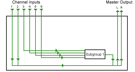
Subgroups are a way to "pre-mix" a number of channels on a sound console before sending them to the master output mix. In the following diagram, channels 1 and 2 are assigned directly to the master output bus. Channels 3,4,5 and 6 are assigned to subgroup 1, which in turn is assigned to the master output.
Subgroup Diagram
Subgroups have many uses and advantages, the most obvious being that you can pre-mix (sub-mix) groups of inputs.
For example, if you have six backing vocalists you can set up a good mix just for them, balancing each voice to get a nice overall effect. If you then send all six channels to one subgroup, you can adjust all backing vocals with a single subgroup slider while still maintaining the balance between the individual voices.
Note that if your mixing console's subgroups are mono, you will need to use them in pairs to maintain a stereo effect. For each pair, one subgroup is the left channel and the other is right. Each channel can be panned across the two subgroups, while the subgroups are panned completely left and right into the master output bus.

Sound Mixers: Channel Faders

Sound Mixers: Channel Faders

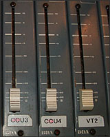
Sliders / FadersEach channel has it's own fader (slider) to adjust the volume of the channel's signal before it is sent to the next stage (subgroup or master mix).
A slider is a potentiometer, or variable resistor. This is a simple control which varies the amount of resistance and therefore the signal level. If you are able to look into the inside of your console you will see exactly how simple a fader is.
As a rule it is desirable to run the fader around the 0dB mark for optimum sound quality, although this will obviously vary a lot.
Remember that there are two ways to adjust a channel's level: The input gain and the output fader. Make sure the input gain provides a strong signal level to the channel without clipping and leave it at that level — use the fader for ongoing adjustments.

Sound Mixers: PFL

Sound Mixers: PFL

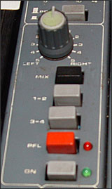
Channel Assign Buttons and Pan ControlPFL means Pre-Fade Listen. It's function is to do exactly that — listen to the channel's audio at a point before the fader takes effect. The PFL button is usually located just above the channel fader. In the example on the right, it's the red button (the red LED lights when PFL is engaged).
Note: PFL is often pronounced "piffel".
When you press the PFL button, the main monitor output will stop monitoring anything else and the only audio will be the selected PFL channel(s). This does not affect the main output mix — just the sound you hear on the monitor bus. Note that all selected PFL channels will be monitored, so you can press as many PFL buttons as you like.
PFL also takes over the mixer's VU meters.
PFL is useful when setting the initial input gain of a channel, as it reflects the pre-fade level.

PFL vs Solo

PFL is similar to the solo button. There are two differences:
  1. PFL is pre-fader, solo is post-fader (i.e. the fader affects the solo level).
  2. PFL does not affect the master output but soloing a channel may do so (depending on the mixer).

Sound Mixers: Channel Assigning & Panning One of the last sets of controls on each channel, usually just before the fader, is the channel assign and pan. Pan Control Pan Almost all stereo mixers allow you to assign the amount of panning. This is a knob which goes from full left to full right. This is where the channel signal appears on the master mix (or across two subgroups if this is how the channel is assigned). If the knob is turned fully left, the channel audio will only come through the left speaker in the final mix. Turn the knob right to place the channel on the right side of the mix. Assign This option may be absent on smaller mixers but is quite important on large consoles. The assign buttons determine where the channel signal is sent. In many situations the signal is simply sent to the main master output. In small mixers with no assign controls this happens automatically. However you may not want a channel to be fed directly into the main mix. The most common alternative is to send the channel to a subgroup first. For example, you could send all the drum microphones to their own dedicated subgroup which is then sent to the main mix. This way, you can adjust the overall level of all the drums by adjusting the subgroup level. Channel Assign Buttons and Pan ControlIn the example pictured right, the options are: * Mix: The channel goes straight to the main stereo mix * 1-2: The channel goes to subgroup 1 and/or 2. If the pan control is set fully left the channel goes only to subgroup 1, if the pan is set fully right the channel goes only to subgroup 2. If the pan is centered the channel goes to subgroups 1 and 2 equally. * 3-4: The channel goes to subgroups 3 and/or 4, with the same conditions as above. For stereo applications it is common to use subgroups in pairs to maintain stereo separation. For example, it is preferable to use two subgroups for the drums so you can pan the toms and cymbals from left to right. You can assign the channel to any combination of the available options. In some cases you may not want the channel to go to the main mix at all. For example, you may have a channel set up for communicating with the stage via an aux channel. In this case you don't assign the channel anywhere.

Sound Mixers: Channel Assigning & Panning

One of the last sets of controls on each channel, usually just before the fader, is the channel assign and pan.
Pan Control

Pan

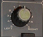
Almost all stereo mixers allow you to assign the amount of panning. This is a knob which goes from full left to full right. This is where the channel signal appears on the master mix (or across two subgroups if this is how the channel is assigned). If the knob is turned fully left, the channel audio will only come through the left speaker in the final mix. Turn the knob right to place the channel on the right side of the mix.

Assign

This option may be absent on smaller mixers but is quite important on large consoles. The assign buttons determine where the channel signal is sent.
In many situations the signal is simply sent to the main master output. In small mixers with no assign controls this happens automatically.
However you may not want a channel to be fed directly into the main mix. The most common alternative is to send the channel to a subgroup first. For example, you could send all the drum microphones to their own dedicated subgroup which is then sent to the main mix. This way, you can adjust the overall level of all the drums by adjusting the subgroup level.
Channel Assign Buttons and Pan ControlIn the example pictured right, the options are:
  • Mix: The channel goes straight to the main stereo mix
  • 1-2: The channel goes to subgroup 1 and/or 2. If the pan control is set fully left the channel goes only to subgroup 1, if the pan is set fully right the channel goes only to subgroup 2. If the pan is centered the channel goes to subgroups 1 and 2 equally.
  • 3-4: The channel goes to subgroups 3 and/or 4, with the same conditions as above.
For stereo applications it is common to use subgroups in pairs to maintain stereo separation. For example, it is preferable to use two subgroups for the drums so you can pan the toms and cymbals from left to right.
You can assign the channel to any combination of the available options.
In some cases you may not want the channel to go to the main mix at all. For example, you may have a channel set up for communicating with the stage via an aux channel. In this case you don't assign the channel anywhere.

Sound Mixers: Auxiliary Channels

Sound Mixers: Auxiliary Channels

Most sound desks include one or more auxiliary channels (often referred to as aux channels for short). This feature allows you to send a secondary feed of an input channel's audio signal to another destination, independent of the channel's main output.
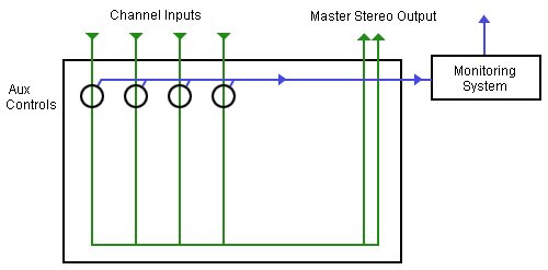
The example below shows a four-channel mixer, with the main signal paths shown in green. Each input channel includes an auxiliary channel control knob — this adjusts the level of the signal sent to the auxiliary output (shown in blue). The auxiliary output is the sum of the signals sent from each channel. If a particular channel's auxiliary knob is turned right down, that channel is not contributing to the auxiliary channel.
 
Auxiliary Channel
In the example above, the auxiliary output is sent to a monitoring system. This enables a monitor feed which is different to the main output, which can be very useful. There are many other applications for auxiliary channels, including:
  • Multiple separate monitor feeds.
  • Private communication, e.g. between the sound desk and the stage.
  • Incorporating effects.
  • Recording different mixes.
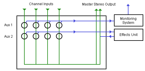
Mixers are not limited to a single auxiliary channel, in fact it is common to have up to four or more. The following example has two auxiliary channels — "Aux 1" is used for a monitor and "Aux 2" is used for an effects unit.
Two Aux Channels
Note that the monitor channel (Aux 1) is "one way", i.e. the channel is sent away from the mixer and doesn't come back. However the Aux 2 channel leaves the mixer via the aux send output, goes through the effects unit, then comes back into the mixer via the aux return input. It is then mixed into the master stereo bus.

Pre / Post Fader

Aux Controls with Pre/Post Selectors The auxiliary output from each channel can be either pre-fader or post-fader.
A pre-fader output is independent of the channel fader, i.e. the auxiliary output stays the same level whatever the fader is set to.
A post-fader output is dependent on the fader level. If you turn the fader down the auxiliary output goes down as well.
Many mixers allow you to choose which method to use with a selector button. The example pictured right shows a mixer channel with four auxiliary channels and two pre/post selectors. Each selector applies to the two channels above it, so for example, the button in the middle makes both Aux 1 and Aux 2 either pre-fader or post-fader.

Sound Mixers: Channel Equalization

Sound Mixers: Channel Equalization

Most mixers have some of sort equalization controls for each channel. Channel equalizers use knobs (rather than sliders), and can be anything from simple tone controls to multiple parametric controls.
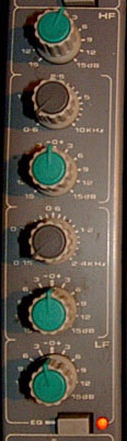
Note: For more general information about equalization see Audio Equalizers.
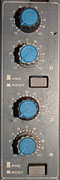
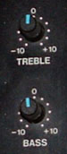
The first example on the right is a simple 2-way equalizer, sometimes referred to as bass/treble or low/high. The upper knob adjusts high frequencies (treble) and the lower knob adjusts low frequencies (bass). This is a fairly coarse type of equalization, suitable for making rough adjustments to the overall tone but is not much use for fine control.
 
This next example is a 4-way equalizer. The top and bottom knobs are simple high and low frequency adjustments (HF and LF).
The middle controls consist of two pairs of knobs. These pairs are parametric equalizers — each pair works together to adjust a frequency range chosen by the operator. The brown knob selects the frequency range to adjust and the green knob makes the adjustment.
The top pair works in the high-mid frequency range (0.6KHz to 10KHz), the lower pair works in the low-mid range (0.15 to 2.4KHz).
The "EQ" button below the controls turns the equalization on and off for this channel. This lets you easily compare the treated and untreated sound.
It is common for mixers with parametric equalizers to combine each pair of knobs into a single 2-stage knob with one on top of the other. This saves space which is always a bonus for mixing consoles.

Notes About Channel Equalization

If the mixer provides good parametric equalization you will usually find that these controls are more than adequate for equalizing individual sources. If the mixer is limited to very simple equalization, you may want to use external equalizers. For example, you could add a graphic equalizer to a channel using the insert feature.
In many situations you will use additional equalization outside the mixer. In live sound situations, for example, you will probably have at least one stereo graphic equalizer on the master output.

Tone Frequency Duration Download:

Download Audio Tone Files

The audio test tones below are available for free download and use in your projects. Select the tone you wish to download and click the corresponding format of your choice. All files are mono, sampled at 44100Hz, 16-bit. If you're not sure which tone you want, 1kHz is a safe bet.
Tone Frequency Duration Download:
100Hz 0:05.00 wav (0.4MB) mp3 (0.1MB)
  0:30.00 wav (2.5MB) mp3 (0.5MB)
250Hz 0:05.00 wav (0.4MB) mp3 (0.1MB)
  0:30.00 wav (2.5MB) mp3 (0.5MB)
440Hz 0:05.00 wav (0.4MB) mp3 (0.1MB)
  0:30.00 wav (2.5MB) mp3 (0.5MB)
1kHz 0:05.00 wav (0.4MB) mp3 (0.1MB)
  0:30.00 wav (2.5MB) mp3 (0.5MB)
10kHz 0:05.00 wav (0.4MB) mp3 (0.1MB)
  0:30.00 wav (2.5MB) mp3 (0.5MB)

demo

Free Download Audio Samples
Free sample test tones are provided in 160k MP3 format. For each of the 3 tones on this page is the associated spectrogram. The spectrogram shows the frequency and amplitude of each file. Note the tight response of the warble tone vs the smooth averaging and rolloff of the 1/3 octave pink noise.
The CDs sold on this site, as well as the files available for download to paid members, are full 16bit uncompressed WAV files.
1 khz fixed test tone -14dbfs
1KHZ sine wave spectrogram
1 khz centered warble tone ( 700 to 1300 hz )
1KHZ warble tone spectrogram
1 khz centered 1/3 octave pink noise
1KHZ 3rd octave spectrogram

Test audio

Low Cost Flat Profile Microphone - You can spend a thousand or you can spend a lot less. For all intents and purposes you'd be hard pressed to find anyone who could tell by listening HOW you aligned your system - but they'll definitely notice how good it sounds. A Flat Mic takes the guesswork out of aligning and testing your system and, when used with a spectrum analyzer, can quickly diagnose audio problems.
What's in it for you? Lower cost, free access to all our test tones, our spectrum analyzer software, and, what you've really come for, - A Great Sounding System!
At the center of any audio alignment job is a good 'ear'. This ear is usually a flat response microphone and an audio spectrum analyzer. Testaudio.com offers a low cost alternative to both.
How To Buy The Flat Mic. Order the flat mic, kit or complete, and get FREE 30 day access to our downloadable files and software ( an $18 value ).
Buy Complete Mic - You'll get a fully assembled and tested flat mic along with spectrum analyzer software on cd, BIN FFT test tones on CD, and 30 days membership to our site to download all our test tones.
Buy DIY Mic Kit - Kit contains the mic housing , one mic capsule, spectrum analyzer software on cd, BIN FFT test tones on CD, instructions, and 30 days membership to our site to download all our test tones. YOU put it together. Requires soldering iron and soldering skills.
Buy Extra Mic Capsules - For the ultimate do it yourselfer. This is the mic capsule only - does not include software, instructions, or membership.
Our microphone offers one of the flatest response curves in the industry. This is due to the carefully selected element used. Here's the typical response curve of a normal pc microphone:

Here's our modified microphone:

As you can see our mic is superior and shows only a small deviation in the 8khz range which is typically less then 3db - a margin of audio error that most humans can not perceive.
We offer our flat mic as a complete ready to go flat mic or as a "do it yourself" kit for those of you looking to save a few bucks. The kit requires some soldering and takes only a few minutes to complete.

Do It Yourself (DIY) INSTRUCTIONS

For those choosing the KIT version we're including the instructions on this page. Complete assembly should take less than 30 minutes.
Unmodified Mic: On the left is the mic housing we've selected. We chose this model because it's very easy to open the end and replace the existing capsule. The image on the right shows 3 capsules. Your kit contains 1 capsule.

Disassemble the microphone: There's a small cap on the end of this mic that is not glued so it's easy to pop off using a small screwdriver, a knife, etc. Once the cap is removed you can pop the old element out. Be careful not to rip the wires apart - there's not much room here and what's shown below is about all the wire you have to play with.

Replace the mic capsule: Here I've placed the mic in a vise. This is not necessary but makes the job very easy. You'll see 2 wires attached the the mic. The blue lead is ground and the green is signal. De-solder the old mic element and discard.

Now solder in the new element. You'll need to look closely at the element to see which solder tab is ground. One tab (ground) has a small trace connecting in to the mic casing and the other (signal) does not. You'll want to solder the blue wire to the ground tab of the mic element. I've placed the element in the vise to make soldering easier.

Reassemble the microphone. Push the element into the housing ( make sure the black front of the mic element faces front) and pop the cap back on. You're now ready to use your new flat mic and align your system.

The product is an Electret condenser microphone intended for operation with a pc sound card. Non supported configurations may require additional hardward. Please refer to your product's technical manual for details.

analog system

SR1

Audio Analyzer
SR1 — 200 kHz dual-domain audio analyzer
  • ≤-112 dB THD+N (analog system at 1 kHz, 20 kHz BW)
  • 200 kHz (signal generation & measurements including FFTs)
  • ≤-118 dBu analog analyzer noise ( 20 kHz BW)
  • ±0.008 dB flatness (analog system, 20 Hz to 20 kHz)
  • Low Crosstalk ( ≤-140 dB analog inputs)
  • ≤600 ps jitter (50 Hz to 100 kHz)
  • Dual-Channel FFTs


SR1 Dual-Domain Audio Analyzer is a stand-alone instrument that delivers cutting edge performance in a wide variety of audio measurements. With a versatile high-performance generator, an array of analyzers that operate symmetrically in both the analog and digital domains, and digital audio carrier measurements at sampling rates up to 192 kHz, SR1 is the right choice for the most demanding analog and digital audio applications.
User Interface
SR1 uses an integrated computer running the Windows XP embedded operating system, so operation will be immediately familiar and intuitive. Depending on the application, SR1 can be operated with an external mouse and keyboard, or by using the front-panel knob, keypad and touchpad.
Seven on-screen tabbed pages are available for arranging panels, graphs, and displays. Screen setups, data, and instrument configurations can be quickly saved and recalled to either the internal hard disk or to a flash drive connected to one of the two front-panel USB connectors. An optional 1024 x 768 XVGA monitor (opt. 02) provides better resolution and allows more information to be displayed.
While SR1’s configuration panels offer total flexibility in setting up every detail of the analyzer, at times it is useful to get a measurement going quickly, without worrying about infrequently used parameters. That’s where QuickMeas comes in. QuickMeas gives SR1 users the ability to get up and running on many common audio measurements such as Level, SNR, Frequency Response, and Crosstalk after answering just a few simple questions about the inputs and outputs of the DUT. When the measurements are finished, the results are available in a clear, easy-to-understand report.

Analog Signal Generator
At the heart of SR1 is a uniquely flexible analog signal generator. All of the standard audio waveforms are available including sine, log-swept sine chirp, synchronous burst sine, noise (white, pink, and filtered), standard intermodulation test signals (SMPTE, CCIF, DIM), square waves, arbitrary waveforms (ASCII and .WAV), ramps and multitone waveforms. Many of these signals can be combined in the generator allowing you to create an unlimited number of test waveforms.
But the analog signal generator doesn’t sacrifice performance for flexibility. With a flatness of ±0.008 dB (20 Hz to 20 kHz) and a residual THD+N of -106 dB (20 Hz to 20 kHz), SR1’s Low Distortion Sine rivals the performance of any analyzer.
Multitone waveforms with up to 50 tones, each adjustable in frequency, amplitude, and phase are calculated and loaded in real-time, without having to run a cumbersome off-line program to generate arbitrary waveform tables. A convenient FFT Chirp waveform is automatically synchronized to the FFT analyzer allowing instant FFT measurements of frequency response (magnitude and phase).

Digital Audio Signal Generator
The same flexibility and performance is found in SR1’s digital audio signal generator. Almost all the same waveforms found in the analog generator are available in the digital generator with the addition of several special digital test waveforms including digital constant, walking bits, and a staircase waveform (for D/A testing).
The digital audio output sampling rate is continuously adjustable from 24 kHz to 216 kHz (single and dual connector). Full control over transmitted status bits (in both professional and consumer formats), user bits, and validity bits, is provided.
For digital interface testing, a variety of impairment signals can be imposed on the digital audio carrier. Carrier impairments include variable rise time (5 ns to 400 ns), common mode sine waves, normal mode noise, and several jitter waveforms (sine, square, and noise).
Timebase
All of SR1’s sampling clocks are derived from an internal timebase with 5 ppm accuracy. For the most demanding applications, an optional atomic rubidium (FS725) timebase is available with an accuracy at shipment is ±5 x 10-11, and a 20-year aging specification of less than 5 ppb. Additionally, the timebase may be synchronized to an external clock, an AES11 reference signal, or any standard video signal.
Analyzers
The heart of SR1’s measurement abilities is its versatile set of analyzers which operate symmetrically on both analog and digital audio signals with no need to purchase additional options. Up to two analyzers can be run simultaneously on either the analog or
digital inputs.
The Time Domain Detector makes all of the standard audio measurements including Amplitude, Crosstalk, and THD+N. Continuously variable bandwidth limiting and standard weighting filters are included. The post notch-filter distortion signal can be fed to an FFT analyzer for a live spectral display of distortion, or to the rear-panel monitor output or speaker.
The Single-Channel FFT and Dual-Channel FFT Analyzers offer live spectral displays with full zoom and heterodyne capability. The full resolution of the analyzer can be applied to any frequency range down to 1/512th of the full measurement bandwidth, leading to an effective resolution of 16M FFT lines. Several averaging algorithms can be applied to bring out low level signals.
The two-channel FFT analyzer offers true single-shot frequency response measurements for the ultimate in accuracy. SR1 also has a complete set of impulse response measurements including impulse response, quasi-anechoic frequency response, and energy time-. curve. Since SR1 is a true two-channel FFT, it isn't limited to MLS waveforms, but can use virtually any waveform.

The THD Analyzer makes frequency selective THD measurements on two user-selectable sets of up to 13 harmonics of the input signal.
The IMD Analyzer makes standard audio distortion measurements including SMPTE, CCIF, and DIM. Frequency selective analysis ensures high measurement accuracy.
The Histogram Analyzer displays live histograms of input signal amplitudes and probability distributions. Realtime fits to Gaussian distributions can be generated.
The Multitone Analyzer, in combination with the Multitone Generator, can be configured to make fast single-shot measurements of a variety of audio parameters including Level, Frequency Response, THD+N, THD Total Distortion, Noise, Crosstalk, and IMD.
DIgital Audio Interface Measurements
SR1 provides a complete set of measurements for digital interface testing. Carrier level and sampling frequency are measured directly. Status bits are fully decoded in both professional and consumer formats, and user bits are displayed as well. SR1’s Jitter Analyzer measures jitter in both the time and frequency domain, including continuously variable bandwidth limiting and weighting in both domains. For frequency domain measurements, live zoomable and heterodyned spectral displays of jitter are available. With a residual jitter of only 600 ps, the performance of SR1’s jitter analyzer is unbeatable.
Digitizer
An optional 80 MHz transient digitizer (opt. 01) provides additional digital audio carrier analysis. Operating on a record of up to 2M samples, the digitizer computes and displays the time record of the input signal and its jitter, input spectrum, jitter spectrum, and the probability distributions of the input and jitter amplitudes as well as the pulse width and pulse rate. Full color eye-diagrams can be generated allowing easy testing against user-configurable eye limits.
Automation and Programming
SR1 offers unprecedented flexibility for user scripting and remote programming. On-board scripts can be written in VBScript, Jscript, or Python with full access to all of the instrument’s capabilities as well as the ability to create simple user-interfaces for running tests. SR1 has a complete hierarchical GPIB command set, and GPIB commands can be sent over the standard IEE-488 interface, RS-232 port, or over the Ethernet on a TCP/IP network (VXI-11). Finally, SR1 has a complete COM interface allowing instrument operation to be automated from any COM capable application such as Visual Basic, LabView, or Microsoft Office.


Specifications
Analog Signal Generator
 
General Characteristics


Amplitude Range (rms) 1 µV to 28.3 V (balanced)
1 µV to 14.1 V (unbalanced)
Amplitude Accuracy ±0.5 % (±0.043 dB) at 1 kHz
Frequency Range  
     Hi BW DAC 10 Hz to 200 kHz
     Hi Res DAC 10 Hz to 0.45Fs (Fs: 128 kHz or
64 kHz fixed, 24 kHz to 216 kHz adj.)
Frequency Accuracy ±0.0005 % (5 ppm)
Frequency Resolution 24
Output Configuration Balanced Ground, Balanced Float, Unbalanced Ground, Unbalanced Float, Common Mode Test

Source Impedance 50 Ω, 150 Ω, 600 Ω (balanced)
25 Ω, 75 Ω, 600 Ω (unbalanced)
Max. Power (600 Ω load)  
     Balanced 30.5 dBm
     Unbalanced 24.9 dBm
Float Voltage ±40 V
Crosstalk  
     10 Hz to 20 kHz -125 dB
     >20 kHz -100 dB
 
Waveforms
   
Low Distortion sine (Hi BW DAC)  
Flatness  
     20 Hz to 20 kHz ±0.020 dB (typ. ±0.012 dB)
     10 Hz to 64 kHz ±0.025 dB
     10 Hz to 200 kHz ±0.05 dB
Residual THD+N (Hi BW DAC)  
     1 kHz, 4 Vrms -112 dB (22 kHz BW)
     20 Hz to 20 kHz -106 dB + 1 µV (22 kHz BW)
  -100.5 dB + 1.7 µV (80 kHz BW)
  -97 dB + 2.5 µV (200 kHz BW)
     10 Hz to 100 kHz -89 dB + 2.5 µV (200 kHz BW)
Residual THD+N (Hi Res DAC, Fs = 128 kHz)  
     1 kHz, 4 Vrms -112 dB (22 kHz BW)
     20 Hz to 20 kHz -106 dB + 1 µV (22 kHz BW)
     20 Hz to 57.6 kHz -102 dB + 1.4 µV (57.6 kHz BW)
Residual THD+N (Hi Res DAC, Fs = 64 kHz)  
     1 kHz, 4 Vrms -112 dB (22 kHz BW)
     20 Hz to 20 kHz -106 dB + 1 µV (22 kHz BW)
 
Regular Sine
Flatness (rel. to 1 kHz, amplitude ≤4 Vrms)  
     20 Hz to 20 kHz ±0.008 dB (typ. ±0.003 dB)
     10 kHz to 64 kHz ±0.02 dB
     10 Hz to 200 kHz ±0.03 dB
Residual THD + N (Hi BW DAC)  
     1 kHz -86 dB (22 kHz BW)
     22 Hz to 20 kHz -85 dB + 1 µV (22 kHz BW)
  -84.5 dB + 1.7 µV (80 kHz BW)
  -82 dB + 2.5 µV (200 kHz BW)
     10 Hz to 100 kHz -77 dB + 2.5 µV (200 kHz BW)
Residual THD+N (Hi Res DAC, Fs = 128 kHz)  
     1 kHz -99 dB (22 kHz BW)
     22 Hz to 20 kHz -98 dB + 1 µV (22 kHz BW)
     20 Hz to 57.6 kHz -96.5 dB + 1.4 µV (57.6 kHz BW)
Residual THD+N (Hi Res DAC, Fs = 64 kHz)  
     1 kHz -106 dB (22 kHz BW)
     22 Hz to 20 kHz -101 dB + 1 µV (22 kHz BW)
Phased Sines 0 to 360°, 0.001° resolution
   
IMD SMPTE/DIN, CCIF/DFD, DIM/TIM
 
Noise White, Pink, Filtered White/Pink, USASI
 
Multitone 1 to 50 tones
   
MLS Repetition rates from 28 to 220
 
FFT Chirp Equal power in each FFT bin
   
Log-swept sine chirp Swept-sine with log increasing frequencies
 
Square 10 Hz to 50 kHz frequency range
 
Ramp Fs/N frequency range (N≥20)
 
Arbitrary 256 Samples to 136k Samples
 
Polarity 10 Hz to Fs/4 frequency range
 
Constant (Offset) DC to 20 Vp (unbal) / 40 Vp (bal)
 
Bursts  
Burst Types Timed, externally triggered, externally gated, synchronous sine, shaped
 
Digital Audio Signal Generator
 
Digital Audio Carrier Characteristics
   
Output Amplitude  
     Balanced  
          Range 16 mV to 10.2 V (110 Ω load)
          Accuracy ±10 % + 80 mV
     Unbalanced  
          Range 4 mV to 2.55 V (75 Ω load)
          Accuracy ±10 % + 20 mV
Output Format Balanced XLR (AES/EBU), dual-connector XLR, unbalanced BNC (SPDIF-EIAJ),dual-connector BNC, Optical (Toslink)
Output Sample Rate 24 kHz to 216 kHz
Sample Rate Accuracy ±5 ppm
Output Impedance 110 Ω (balanced), 75 Ω (unbalanced)
 
Digital Audio Waveforms
   
Sine  
Frequency Range 10 Hz to Fs/2
Frequency Resolution 24
Flatness ±0.001 dB
Harmonic/Spurious -148 dB.
 
Phased Sine 0 to 360° range, 0.01° resolution
 
Square 10 Hz to Fs/2 frequency range
 
IMD SMPTE/DIN, CCIF/DFD, DIM/TIM
 
Noise White, Pink, Filtered White/Pink, USASI
   
MLS Repetition rates from 28 to 220
 
Ramp Fs/N frequency range (N≥20), adjustable rise/fall fraction
 
Arbitrary 256 Samples to 136k Samples
 
FFT Chirp Equal power in each FFT bin. Frequency response can be modified with an EQ file.
   
Log-swept sine chirp Swept-sine with log increasing frequencies
 
Polarity 10 Hz to Fs/4 frequency range
 
Bursts  
Burst waveforms All allowed waveforms
Burst types Timed
Dither None, triangle and rectangular probability distribution
 
Digital Audio Carrier Impairments
   
Jitter  
Waveforms Sine, square, uniform noise, BP filtered noise, chirp
Frequency Range 2 Hz to 200 kHz
Amplitude Range 0 UI to 13 UI
 
Normal Mode Noise  
Amplitude Range  
     Unbalanced 0 to 637 mVpp
     Balanced 0 to 2.55 Vpp
 
Common Mode Sine  
Amplitude Range 0 to 20 Vpp (balanced only)
Frequency Range 10 Hz to 100 kHz
 
Cable Simulation Simulates 100 m of digital audio cable
 
Variable Rise Time 5 ns to 400 ns
 
Signal Measurements
 
General Analog Input Characteristics
   
Amplitude Range (rms) 62.5 mV to 160 V
Input Configuration XLR, BNC, Generator Monitor, Digital Audio Common Mode
Input Impedance  
     Balanced 200 kΩ / 95 pF
     Unbalanced 100 kΩ / 185 pF
Input Termination (bal) 300 Ω, 600 Ω, 200 kΩ
Crosstalk  
     10 Hz to 50 kHz ≤-140 dB
     >50 kHz ≤-135 dB
Hi BW ADC  
     Type 16-bit sigma-delta
     Sampling Frequency 512 kHz
     Frequency Range DC to 228 kHz
Hi Res ADC  
     Type 24-bit sigma-delta
     Sampling Frequency 128 kHz or 64 kHz (fixed), 24 kHz to 216 kHz (adj.)
     Frequency Range DC to 0.45Fs
 
General Digital Input Characteristics
   
Input Format Balanced XLR (AES/EBU), dual-connector XLR, unbalanced BNC (SPDIF-EIAJ), dual-connector BNC, Optical (Toslink)
Input Sample Rate 24 kHz to 216 kHz
Input Impedance Hi Z or 110 Ω (balanced)
Hi Z or 75 Ω (unbalanced)
 
Analog Signal Meters
   
RMS Level Meter  
Accuracy (1 kHz ref) ±0.5 % (±0.043 dB)
Flatness (1 kHz ref, Hi BW ADC, Fs=512 kHz)  
     20 Hz to 20 kHz <±0.008 dB (typ. <±0.003 dB)
     10 Hz to 64 kHz <±0.02 dB
     10 Hz to 200 kHz
<±0.03 dB
 
Frequency Meter  
Range 8 Hz to 300 kHz
Accuracy Timebase error ± (2 ppm + 10 mHz)
 
Phase Meter ±1.0° accuracy
 
Digital Signal Meters
   
Frequency Meter 10 Hz to 0.45Fs, ±100 ppm accuracy
 
Phase Meter ±0.05° accuracy
 
Analyzers (Analog and Digital Audio)
   
Time Domain Analyzer  
Measurements Amplitude, amplitude ratio, THD+N, THD+N ratio, SINAD
 
Analog Inputs
   
Amplitude Accuracy ±0.5 % (±0.043 dB)
Flatness (1 kHz ref)  
     20 Hz to 20 kHz <±0.008 dB
     20 Hz to 64 kHz <±0.02 dB
     10 Hz to 200 kHz <±0.05 dB
Residual Noise (62.5 Vrms input range, shorted input)  
     Hi Res ADC (Fs=128 kHz)  
          22 Hz to 22 kHz <-117.5 dBu
          22 kHz to 57.6 kHz <-115 dBu
          A-Weighted <-120 dBu
     Hi BW ADC  
          22 Hz to 22 kHz <-118 dBu
          22 Hz to 80 kHz <-113 dBu
          22 Hz to 200 kHz <-110 dBu
          A-Weighted <-120 dBu
Residual THD+N  
     Hi Res ADC (Fs=128 kHz)  
          1 kHz, 4 Vrms -111 dB (22 kHz BW)
          20 Hz to 20 kHz -107 dB + 0.8 µV (22 kHz BW), -101 dB + 1.3 µV (57.6 kHz BW)
     Hi Res ADC (Fs=64 kHz)  
          1 kHz, 4 Vrms -111 dB (22 kHz BW)
          20 Hz to 20 kHz -107 dB + 0.8 µV (22 kHz BW)
     Hi BW ADC  
          1 kHz -113 dB (22 kHz BW)
          20 Hz to 20 kHz -109 dB (22 kHz BW), -102 dB + 1.5 µV (80 kHz BW), -98 dB + 2.5 µV (200 kHz BW)
          10 Hz to 100 kHz -91 dB (200 kHz BW)
   
Digital Inputs  
   
Amplitude Accuracy ±0.001 dB (at 1 kHz)
Flatness ±0.001 dB (15 Hz to 22 kHz)
Residual THD+N ≤-140 dBFS
   
Bandwidth Limiting Filters  
     Low Pass Filter 4th order Butterworth, adj. from Fs/40 to 0.45Fs, 20 kHz, 40 kHz and 80 kHz fixed elliptical filters per AES17.
     High Pass Filter 4th order Butterworth, @22 Hz, 100 Hz, and 400 Hz. 20 kHz, 40 kHz and 80 kHz fixed elliptical filters per AES17.
     Band Pass Filter  
          Response  
               Hi BW ADC 1/3 Octave, Class II (4-pole)
               Hi Res ADC 1/3, 1/6, 1/12, 1/24 Octave, Class III (6-pole)
          Tuning Range  
               Hi BW ADC 10 Hz to 200 kHz
               Hi Res ADC 10 Hz to 0.44Fs
          Tuning Accuracy ±2.5 %
          Amplitude Accuracy ±0.5 %
Notch Filter  
          Tuning Range  
               Hi BW ADC 10 Hz to 200 kHz
               Hi Res ADC 10 Hz to 0.44Fs
          Tuning Accuracy ±2.5 %
          Response -3 dB at 0.73Fc and 1.37Fc
          Amplitude Accuracy ±0.2 dB (20 Hz to 180 kHz, f<0.5f0 or f>2f0)
Weighting Filters A-wt, C-Msg wt, CCITT, CCIR (weighted, unweighted, & 2 kHz)
Optional Filters Up to 4 per channel (Hi BW only)
Detector Type RMS, Peak, Quasi-Peak (CCIR-468)
   
Single and Dual-Ch. FFT Analyzers  
Frequency Range  
     Hi BW ADC DC to 200 kHz
     Hi Res ADC DC to 0.45Fs
Digital Audio DC to F 2
Number of Lines 256, 512, ... 32k
Processing 40-bit floating point
Windows Blackman Harris, Enhanced Blackman Harris, Hann, Hamming, Equiripple, Flattop, Gaussian, Kaiser, Uniform, Rife Vincent 4, 5 and 10 term
Zoom Span can be narrowed by up to 512x
Heterodyne Narrowed span can be centered anywhere in the measurement range
Averaging Fixed length and continuous
Dual-Ch. Measurements Frequency response, coherence, impulse response
 
THD Analyzer Measures two independent sets of user-selectable harmonics (2x to 14x)
 
IMD Analyzer SMPTE/DIN, CCIF/DFD, DIM/TIM
 
Histogram Analyzer Time vs. amplitude, Histogram, PDF, Gaussian fit to PDF
 
Multitone Analyzer Level, Frequency Response, THD+N, noise, THD, IMD, Crosstalk
   
Digital Audio Carrier Measurements
   
Measurements Carrier amplitude, sample rate, jitter amplitude, jitter spectrum
Sample Rate 24 kHz to 216 kHz
Sample Rate Accuracy ±5 ppm
Carrier Amplitude Measurements  
     Balanced (XLR) ±10 % + 80 mV
     Unbalanced (BNC) ±10 % + 20 mV
Optical Displays voltage of Toslink receiver
Output to Input Delay Measures delay from Digital Audio Output or AES11 reference output to Digital Audio Input
     Range -12.7 UI to +115.1 UI in seconds
     Resolution 60 ns
Residual Jitter  
     50 Hz to 100 kHz ≤600 ps
Reference  
     Input Surces AES11 (24 Hz to 216 kHz), sine or TTL (8 kHz to 32 MHz), video (NTSC/PAL/SECAM)

 
General
   
Computer Interfaces GPIB, RS-232, Ethernet, COM
Digitizer (opt. 1)  
     Sampling Rate 80 MHz
     Acquisition Length 4k, 8k, 16k, 128k, 256k, 512k, 1M, 2M samples
     Measurements Input vs. time, jitter vs. time, input spectrum, jitter spectrum, pulse width/rate histograms, jitter probability histogram, eye diagrams
Video Out VGA output for driving external monitor
Power <250 W, 90 VACto 264 VAC, 47 Hz to 63 Hz
Dimensions 17" × 8.5 " × 20.25 " (WHD)
Weight 40 lbs.
Warranty One year parts and labor on defects in materials and workmanship