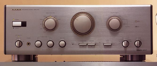
| ONKYO Integra A-917 | |
| 85,000yen(around the 1990 time) |
The Integrated Amplifier put on the market as a new Integra series of the 90s.
The "current-drive amplifier" which is current amplification type amplifier was carried in the output stage, and the super current amplifier structure which coalesced the "BI-MOS drive scheme" in this is adopted.
With current-drive amplifier, a V-I translation is completed on the stage in front of an output stage, and it has the composition of making an electric current amplifying at the output stage.
Thereby, it is not influenced by exothermic of an output transistor, either but the current amplification operation in the status that it was stabilized extremely is enabled.
And a BI-MOS drive scheme is a stream composition which pulls out the strength of MOS FET and a bipolar transistor. A small electric-current area shows the property of a riser curve with loose MOS FET with the incrementation in input voltage. In a large-current area, the property of a bipolar transistor becomes dominant.
Thereby, the property near a linear line could be acquired in the crossover area, and also the linearity which has an elongation also in the time of a large swing is realized.
With super current amplifier, it has a structure which adopted as the output-stage preceding paragraph the BI-MOS drive scheme which performs a "voltage -> electric-current" translation.
A + side - side makes into a perfect symmetrical whole page push pull specification the stage which constitutes power amplifier, and it is suppressing a wave-like asymmetrical distortion.
The LASER transformer which Onkyo developed uniquely is adopted as a power transformer.
The translation core of the new model whose perimeter width is wider than a standard is used for the newly developed LASER transformer. The magnetism to which this leaks from a perimeter part has expanded the width of the perimeter part from 1 to 1.07 by the LASER transformer to having been a ratio called the perimeter 1 to a hub 2 conventionally in the result of having noted the point that electric resistance decreased by making width of a perimeter part large.
Moreover, the perimeter of a core is severely shielded by silicon-steel-plate shielding material, and, as a result, leakage flux is reduced to 1/30 as compared with the conventional EI transformer.
The 2LOAD-RESISTOR-BOX2 splitting bottom chassis structure where a power-source part and other stages were separated is adopted as a chassis structure.
Furthermore, a power stage and a small signal part carry out a block splitting with a heat sink, and guard the interference to a small signal part.
The sub- side coil of the power transformer was separated in the object for power amplifier, and protector circuitries, the subtransformer was carried in - window for microcomputers, the independent power feeding was performed on each stage, and the interference between each stage is eliminated.
In order to reproduce all the music signals in a high purity, the simple direct design which sends a signal into power amplifier direct via a volume for exclusive use is adopted.
If a Source-Direct switchpoint is set to DIRECT, a simple transmit is possible, and if a position is set to TONE, it can adjust in a direct tone.
The remote control functionality which can perform a power source, a volume, an input selector, and a muting from a hand is equipped standardly.
Since the mechanical scheme driven by a motor is used for a volume and an input selector, there is no occurrence of nonlinear distortion like a semiconductor switchpoint.
The capacitor of the power-source part is being firmly fixed by new type chemicon vibration suppression structure material.
It acts as salt Vicor Tyng of the bottom chassis, and it has the structure of suppressing an oscillation.
High-speed diode, a polar attached-indicator AC code and die-casting Detent type volume, etc. are adopted.
The BMC side panel is adopted as a side panel.
|
| Form | LASER transformer loading and super current amplifier |
Output power (20Hz - 20kHz)
compact disk->SP-OUT, both channel drive | 100W+100W (6ohm)
80W+80W (8ohm) |
| Dynamic power | 2ohm: 265W+265W
4ohm: 205W+205W
6ohm: 150W+150W |
| THD (20Hz - 20kHz) | 0.0015% (at compact disk->SP Out, the time of 10W output 8ohm)
0.003% (at the time of Phono man month->Rec Out and 3V output)
0.015% (at the time of Phono MC->Rec Out and 3V output) |
| Cross modulation distortion (20Hz - 20kHz) | 0.004% (at the time of compact disk->SP Out and an Output power) |
| Power Band Width | 5Hz - 100kHz (IHF-3dB, THD 0.2%, 8ohm) |
| Dumping factor | 150 (1kHz, 8ohm) |
| Frequency characteristic | Phono->Rec Out(RIAA deflection): 20Hz-20kHz±0.2dB
compact disk->SP Out: 2Hz-100kHz+0 -0.3dB |
Phono maximum permissible input
(1kHz/10 kHz, 0.005%) | MM:150mV/710mV
MC:9mV/42mV |
| Input sensitivity/impedance | Phono man month: 2.5mV / 47kohm
Phono MC: 160 microvolts/220 ohm
compact disk, Tape Play, Processor IN, other:150mV /, 30kohm |
| An Output-power voltage / impedance | Tape Rec, Processor Out, other:150mV/560 ohm |
| SN ratio (IHF-A filter input short-circuit) | Phono man month: 94dB (5mV input)
Phono MC: 75dB (0.5mV input)
compact disk, other:107dB |
| The tone control maximum variation | Bass: ±10dB (20Hz)
Treble: ±8dB (20kHz) |
| Muting | -20dB |
| Power source | AC100V, 50Hz/60Hz |
| AC outlet | Switched: Two lines, 100W
Unswitched: One line, a total of 100W |
Power consumption
(Electrical Appliance and Material Control Law specification) | 190W |
| Dimensions | Width 455x height 170x depth of 430mm |
| Weight | 17.0kg |
| Adjunct | Remote control |
|
|
.JPG)
.JPG)
.JPG)